Hello everyone,
I would like some help understanding how the “Capture Workflow Start / End” nodes work. The purpose is only for studying.
About those nodes, I decided to do a practical simple test, but I couldn’t execute it successfully.
From what I understand, the purpose of these nodes is to reduce repetition in workflow creation by reusing part of an already created workflow within another workflow. Alternatively, they can be used with a new database file (a file with new data).
Starting my analysis
I found this workflow on the KNIME Hub, and through my analysis, I was able to understand how it works. However, when I tried to apply it more practically, I couldn’t execute it.
Analyzing the workflow
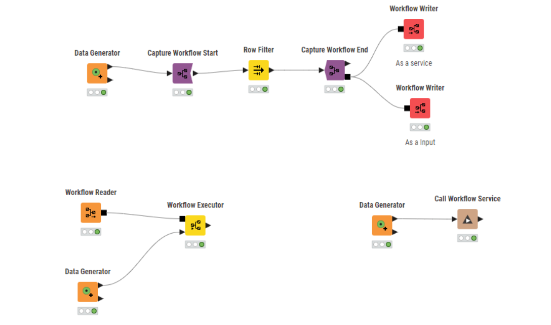
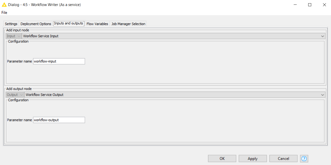
In print1, I see across two groups of Start and End Workflow nodes. These two groups were combined using the “Workflow Combiner” and then saved locally in the specified path.
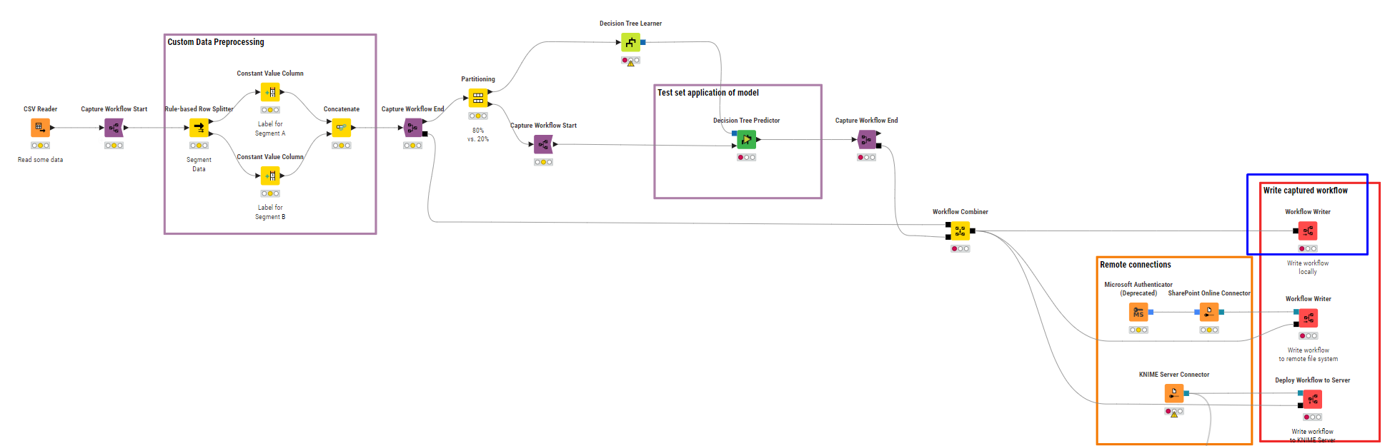
Combiner and Writer
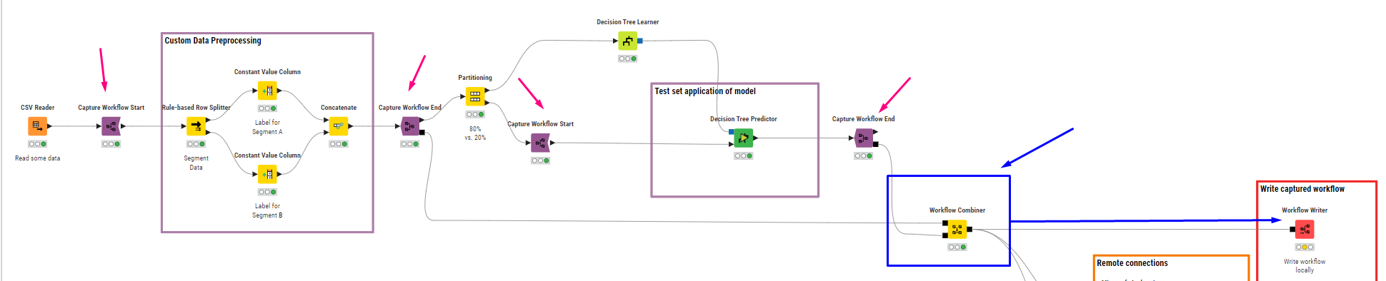
saved workflow
Later, the “Workflow Reader” node was used to read the saved workflow, and then the “Workflow Executor” was used to execute it.

Reading Workflow structure
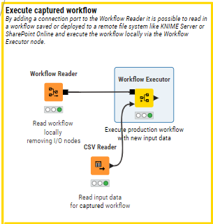
I noticed something interesting: the “Workflow Executor” above…
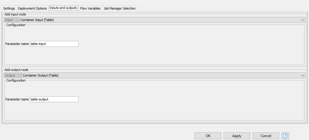
Automatically creates a new port for tables when it detects this type of output in the locally saved workflow.
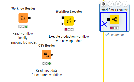
Naturally, the “Workflow Executor” does not have the option to manually create ports, but when connected, it displays the port.
The “Workflow Executor”, does not have option to create ports, but when connected, creates the ports bases on output (it knows everything ![]() )
)
With this in mind, I decided to conduct a test, and this is where I failed.
Explanation of my process
Step 1
I created a table with two columns:
- One column with category values (A, B, C)
- Another column with numerical values
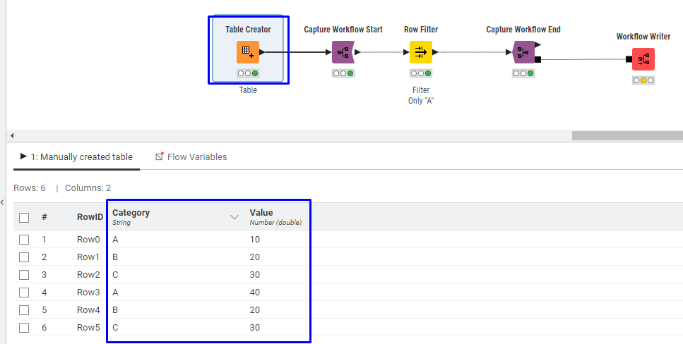
Step 2
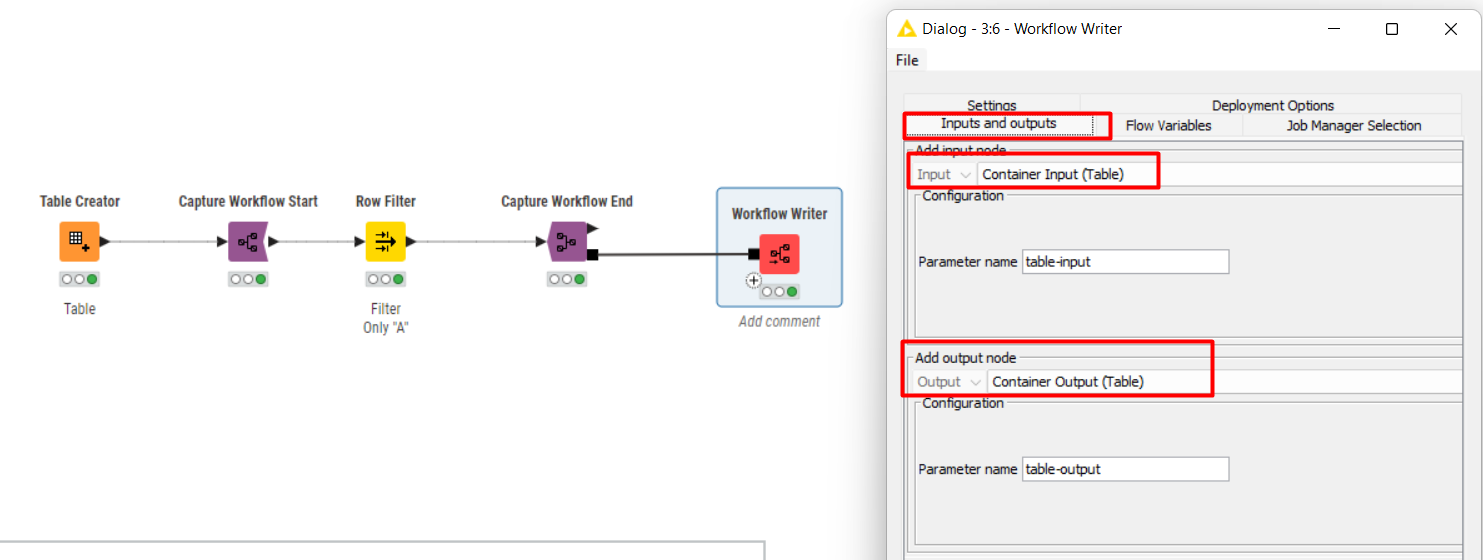
I initiated a Workflow Start.
Step 3
I added a Row Filter and filtered only values in category “A”.
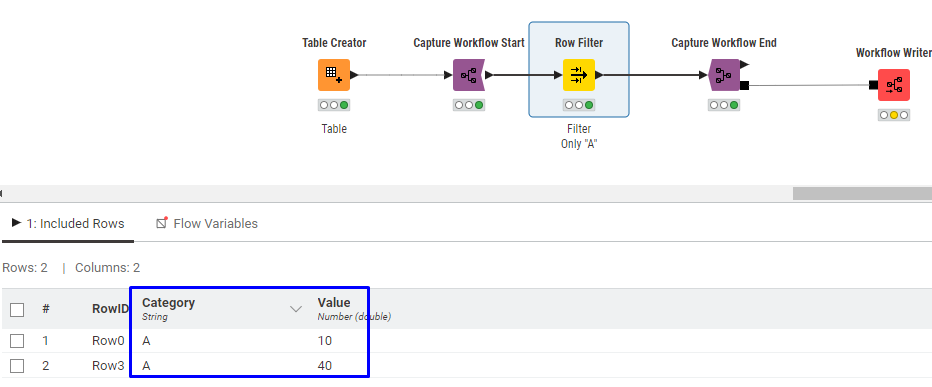
Step 4
I ended with Workflow End.
Step 5
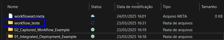
I saved the workflow locally (just like in the KNIME Hub example).
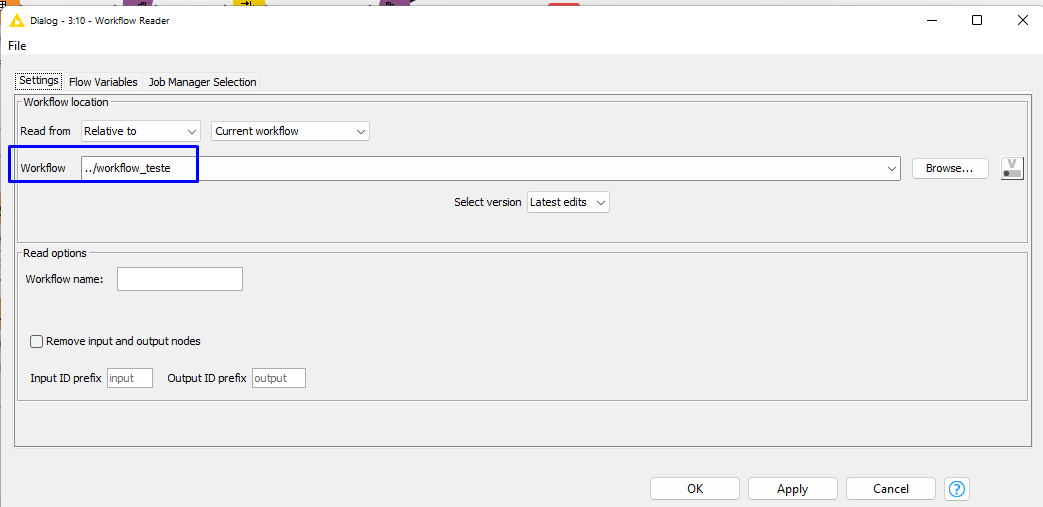
name of file
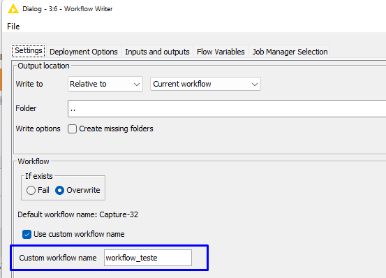
Saved locally
Step 6
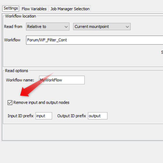
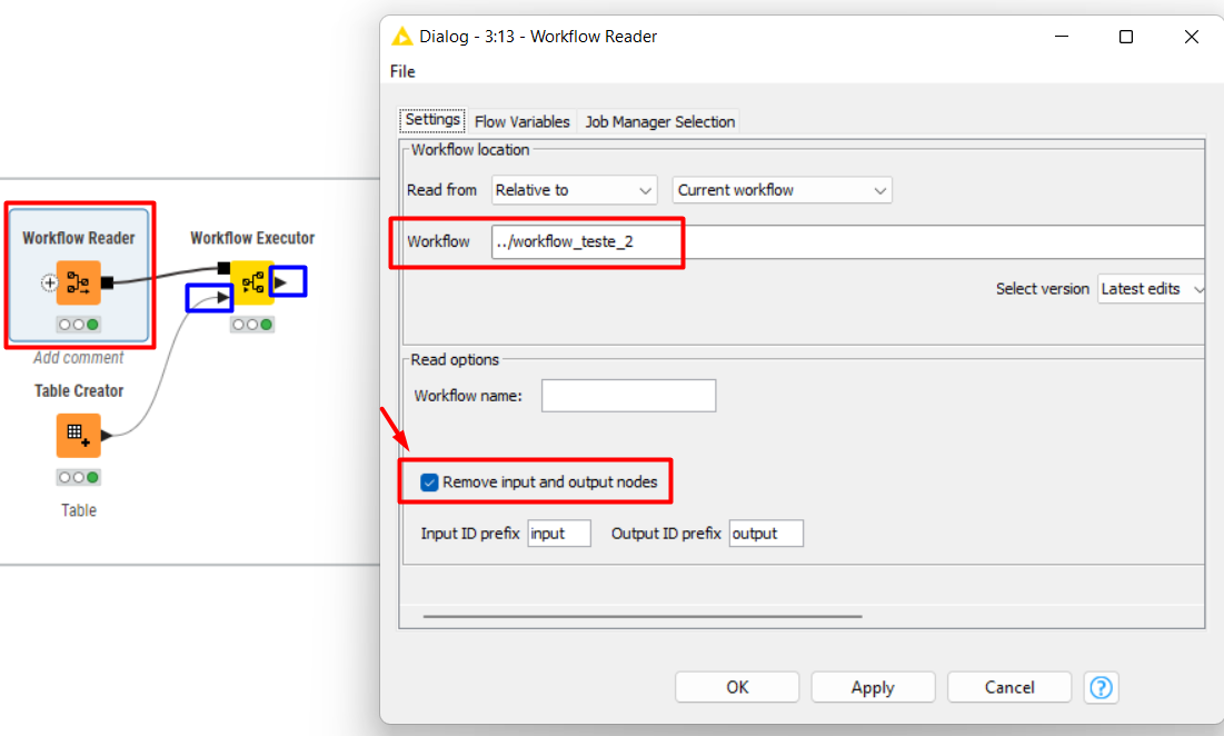
I initiated a Workflow Reader and linked it to the saved file.
Step 7
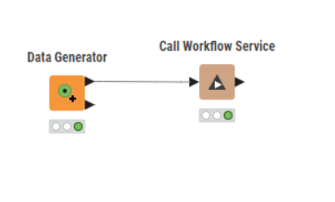
I connected it to the Workflow Executor.
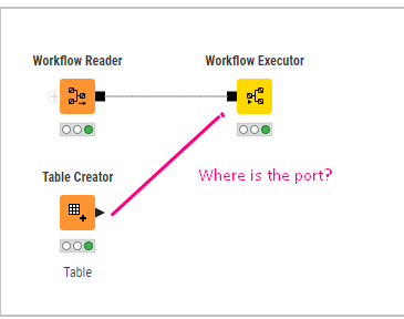
The issue
At this point, I noticed that the “Workflow Executor” did not create the table port.
My question is: Why didn’t this happen?
My objective and expected outcome (in my mind)
My assumption was that I could connect a new table (which is essentially the same table created initially). When executing the Workflow Executor, the result would be the “Row Filter” node applied to category “A”. In other words, I expected it to work like a “component,” but in the form of a Workflow Start / End.
Questions for better understanding:
- Why didn’t my Workflow Writer > Workflow Reader > Workflow Executor create the table port?
- Am I misunderstanding this process?
- Am I using Workflow Start / End incorrectly or in the wrong structural position?
- Is there a simpler example I could use to better understand this concept?
My understanding of “Capture Workflow Start / End”
They remind me a lot of components. A well-structured component, created with no risk of breaking, serves the purpose of streamlining certain routines—accelerating a process that took time to develop and solving a problem efficiently. Once connected to a new or initial database, it handles the processing automatically.
The “Capture Workflow Start / End” nodes work similarly. If you took time to create a solution within a workflow and would like to reuse part of it in another workflow while ensuring it adheres to specific rules to prevent errors, these nodes allow for that. Or not?