New feature ideas: Wireless connector or ghost nodes

Hi

I have been struggling with messy workflows for some time where the same tables are used across many nodes. Unsure if this is posted in the right area

Background
When creating flows with many interdependencies the connector lines tend to create a messy overview of the workflow.

Ideas
I have two suggestions to solve this:

  1. “Wireless” connector that can be toggled on/off
  2. “Ghost node” that is a reference copy of another node but can be placed elsewhere in the flow

Hope to see this in the analytics platform some day, it will really make a big difference

Many thanks
Martin

10 Likes

Yes, a very useful and handy feature (wireless connector), already avaible on Alteryx platfom.
What do you mean by ghost node?

Luca

The ghost node is thought of as a clone of the original node. So rather than taking a copy, you could have a clone of the node with the same output data somewhere else in the workflow, but without all the ingoing connectors and all settings are in the same.

Hello @mmcmcmc,

I agree with you and it is already on the list (Internal reference: AP-12016).

Br,
Ivan

3 Likes

excellent idea.
you can add a +1 to your tracker :smiley:

Hello @docminus2,

done :slight_smile:

Br,
Ivan

1 Like

I agree with the need for options to tidy up workflows - metanodes and components aside. In my experience with Alteryx however, I ended up just trying to look for the wireless input nodes - so wouldn’t call wireless connectors a perfect solution!

I have a couple more asks along the same lines (no pun):

  1. Another thought is if Eclipse has the facility of “layers” (like CAD tools), it may be an even more robust type of option than wireless. Besides the connector lines, there are so many checks and balances that sometimes need to be entered to ensure the data is doing what it is meant to. If these could be put onto layers, and toggled on/off hidden from view until selected, it would help cleanup workflows.
  2. Checks and balances are unruly to keep an eye on. Can there be a facility to keep all checks and balances together in one place, so at a quick glance you can see the data is what it is meant to be? In Excel there is a feature called the Watch window, which allows you to keep an eye on key cells in a separate window. Those cells can be labelled so it is easy to track. See image below:
    image
  3. Row count by hovering over the output arrows of nodes - can these be toggled to stay on or off for specific nodes, or all nodes? Joiners and splitters would benefit most from these. See an sample from Anylogic just for demonstration purposes:
    image

Hope these are considered useful features by others?

3 Likes

Hello @supersharp,

here are my thoughts/comments:

  1. Not sure I understand. Can you explain it a bit more?
  2. Do you know about Node Monitor view? Although doesn’t offer row and column counters (yet!) can be used as indicator of what is going on with flow and data.
  3. Personally don’t like it from workflow visualization point of view but agree joiners,filters and splitters would benefit from it a lot.

Seems to me you could benefit from a “Workflow Monitor” view which can be customized to your need. Maybe this is not a bad idea…

Br,
Ivan

Hi @ipazin

  1. For CAD models, lets say they are designing a house. There will be a layer for the wall, another for plumbing, another for electrical. You can toggle the layers on and off to see one thing at a time, or all at one go. This could be helpful for checks all over the place.
  2. Node monitor is great - for one node at a time. The challenge I have is I have to keep an eye on many nodes to flag when issues occur, so this means flipping between node monitor views. See image sample below. Right now, there is no way to keep an eye on all of these at the same time.
  3. Ability to toggle on/off the row counters might be helpful for certain nodes

Just my thoughts in terms of user experience :slight_smile:

2 Likes

Hello @supersharp,

Tnx for additional explanation. Although still don’t understand how would first point be mapped to KNIME I overall understand much better what are you talking about. Will forward your feedback.

Br,
Ivan

1 Like

Hi @ipazin,

+1 for wireless node connections, please.

Hello @larine,

request noted.

Br,
Ivan

1 Like
  • 1 for wireless node connections

@Sivasanmugam done.
Ivan

I’m always up for a fun challenge :wink: So I started wondering about how “wireless” or “ghost” connectors might be implemented in some way using nothing but the existing Knime nodes, and components built from them.

After pondering on how something usable might be achieved here is what I came up with (albeit with a few warnings about probably not using it with very large datasets, or where you have columns or flow variables that are anything other than Strings, Numbers or Dates - this is just a bit of fun / proof of concept after all!)

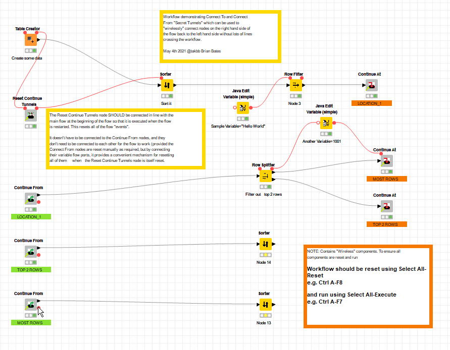
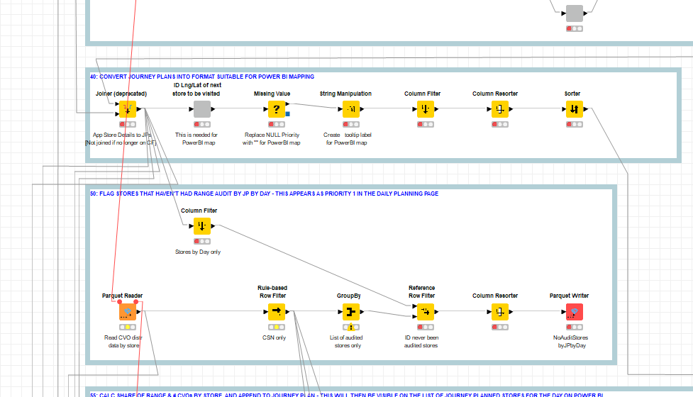
And I present to a fanfare of excitement… my never-before-seen poor person’s wireless node demo workflow:

Provided the workflow is run from an All-reset state, and is run using Ctrl-A - F7 (select all - execute)… the workflow will run, with wireless jumps from the right hand side to the left, and the nodes will run in the correct order, with the expected results and flow variables arriving at the two sorter nodes at the bottom! :slight_smile: (fingers crossed)
There… I bet you’re as excited as I was… enjoy!
Demo Continue Tunnels.knwf (478.4 KB)

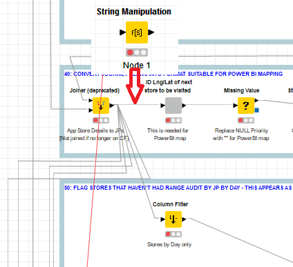
My “Continue At”… “Continue From” components sit somewhere between the concepts of a wireless connection and the “ghost nodes” mentioned above.

For those that want to know… passing of data and flow variables is achieved by parking them into the available H2 database using tables based on the name specified in the config for each node. This is stored in memory (hence possible limitations on dataset size and variable types)

Orchestration is performed by use of WAIT nodes, that wait for a local file modification using a file of the name specified in the config for each node. The file change is made by the “Continue At” node and this signals that it is “clear to proceed” to the “Continue From” node assigned to that same name.

The “Reset Continue Tunnels” node simply clears all flag files in a subfolder beneath the workflow’s local data area.

A bit of fun, and definitely a “proof of concept” toy with some limitations, but I might even use them on some of my own workflows.

(and still a +1 from me for real implementation of wireless connections)

9 Likes

Cool way of using a fast H2 embedded database! Still looking forward to the official implementation :slight_smile:

2 Likes

Hello @takbb,

great idea! Just thinking if it can be simplified somehow…
Request noted.

Br,
Ivan

2 Likes

Another +1 for wireless connectors please.

My rationale is:
a. Large workflows get messy with connectors going all over the place, particularly if I am re-using the output of one node as a ‘temporary table’ input for multiple other nodes.
b. I waste lots of time trying to neaten up the workflow by re-routeing connectors - see below for example:

I wonder if the solution could be as simple as users being able to choose between changing the colour of a connector from black to white (and therefore effectively invisible), but when selecting the node it’s input/outputs turn dark black (thereby exhibiting exactly the same behaviour as they do currently when selected) which means you can quickly see which nodes feed into it.

Thanks,
Dom

1 Like

Hello everyone, I was unaware of this thread. I just saw it cause it bumped up cause someone (@dpowyslybbe ) added a comment to it.

First of all, @takbb , what you did is quite innovative, good job man!

When the workflow is huge, it can indeed get messy, but I usually handle this with metanodes.

The one thing that I can’t manage is, let’s say we take the example workflow from @dpowyslybbe , and I figured at that point, there is a String Manipulation that’s required, and it makes sense that it’s done right after the Joiner, before the result is forked, so that I don’t have to do the String Manipulation at all the forked node:
image

When it’s a single connection, I know I can drag the node on the connection between 2 nodes, and the node will be inserted with Knime automatically linking all 3 nodes.

But when it’s like the above, where you got multiple connections to multiple nodes after the joiner, how do I insert that String Manipulation node so that the joiner connects to its input, and all the other connections connects to the output automatically without having to re-attach each connections properly - and good luck with doing this manually.

2 Likes

Also very interested in this from @bruno29a but to date I’ve not found a way other than connecting each connector manually to the node that’s just been added.